JWST Instrument Model Details
The following describes specific details for the various JWST instrument classes. See also the references page for information on data sources.
One general note is that the webbpsf class interfaces do not attempt to exactly
model the implementation details of all instrument mechanisms, particularly for
NIRCam and NIRISS that each have multiple wheels. The
filter attribute of a given class is used to select any and all filters,
even if as a practical matter a given filter is physically installed in a
“pupil” wheel instead of a “filter” wheel. Likewise any masks that affect the
aperture shape are selected via the pupil_mask attribute even if physically
an optic is in a so-called “filter” wheel.
All classes share some common attributes:
filterwhich is the string name of the currently selected filter. The list of available filters is provided as thefilter_listattribute.
image_maskwhich is the name of a selected image plane element such as a coronagraph mask or spectrograph slit, orNoneto indicate no such element is present. The list of available options is provided as theimage_mask_listattribute.
pupil_masklikewise allows specification of any optic that modifies the pupil plane subsequent to the image mask, such as a coronagraphic Lyot stop or spectrograph grating stop. The list of available options is provided as thepupil_mask_listattribute.Each SI has a
detectorattribute that can be used to select among its multiple detectors (if more than one are present in that SI), and adetector_positionattribute which is a 2-tuple giving the pixel coordinates on that detector for the center location in any calculated output PSF. Note that thedetector_positionvalue should be specified using the order (X,Y).The
aperturenameattribute provides the SIAF aperture name used for transforming between detector position and instrument field of view on the sky. By default this will be a full-frame aperture for the currently-selected detector, but you may select any subarray aperture or other aperture named in the SIAF for that instrument. The aperturename will always update automatically when you select a new detector name. For NIRCam and MIRI, the aperturename can also (optionally) automatically update for coronagraphic subarrays if/when a coronagraphic optic is selected for the image or pupil mask. .
Warning
WebbPSF provides some sanity checking on user inputs, but does not strive to strictly forbid users from trying to simulate instrument configurations that may not be achievable in practice. Users are responsible for knowing the available modes well enough to be aware if they are trying to simulate an inconsistent or physically impossible configuration.
JWST Optical Budgets
The total system performance for JWST is tracked in optical budgets for OTE and SI WFE. WebbPSF includes representations of many of these component terms. These can be visualized as plots of OPDs. See Visualizing the JWST Optical Budget.
Optical Telescope Element (OTE)
The JWST Optical Telescope Element consists of the telescope optics that serve all the science instruments and the fine guidance sensor. Most notably, this means the primary, secondary, tertiary, and fast steering mirrors. The OTE contributes to the overall wavefront error (and therefore the aberrations in instrument PSFs) in a few ways:
The limits of precisely manufacturing the mirrors introduce tiny high spatial frequency bumps and ripples of optical path difference
During commissioning, the telescope mirror segments will be aligned and phased as precisely as possible, but small errors in the final aligned configuration will still contribute to WFE
The WFE will vary with field position, which is inherent in the OTE optical design even if perfectly aligned
Aberrations can be introduced by pupil shear or other misalignments between the OTE and each science instrument
These effects are simulated at high fidelity in models maintained by Ball Aerospace, which in turn were used to create the OPD map files for the JWST instruments included in WebbPSF. Specifically, WebbPSF uses information derived from the as-built OTE optical model Revision G (for the static surface figures of each segments) and the overall JWST optical error budget Revision W (for OTE to ISIM misalignments, WFSC residuals, stability, and budgeted uncertainties for both the OTE and SI contributions).
JWST’s optical system has been extremely precisely engineered and assembled. Individual mirrors typically have below 30 nm r.m.s. WFE, and the overall OTE system including alignment tolerances and dynamics is expected to deliver wavefronts of roughly 100 to 150 nm r.m.s. WFE to each of the instruments. This corresponds to Strehl ratios of 90% or better for wavelengths beyond 2 microns.
Further information on JWST’s predicted optical performance is available in “Status of the optical performance for the James Webb Space Telescope”, Lightsey et al., (2014) and “Predicted JWST imaging performance”, Knight et al. (2012).
For each science instrument, if you examine inst.opd_list (where inst is an instance of an instrument model), you will see the filenames for two “predicted” OPDs and a “requirements” OPD map. For example:
>>> nc = webbpsf.NIRCam()
>>> nc.opd_list
['JWST_OTE_OPD_RevAA_prelaunch_predicted.fits.gz',
 'OPD_RevW_ote_for_NIRCam_predicted.fits.gz',
 'OPD_RevW_ote_for_NIRCam_requirements.fits.gz']
As of WebbPSF 1.0, WebbPSF selects the ‘JWST_OTE_OPD_RevAA_prelaunch_predicted.fits.gz’ OPD as the default OPD map for all instruments. This is a significant change from prior versions:
 >>> nc.pupilopd
'JWST_OTE_OPD_RevAA_prelaunch_predicted.fits.gz'
Performance predictions for a large active deployable space telescope are inherently probabilistic, and Monte Carlo methods have been used to derive overall probability distributions based on the individual error budget terms. The “prelaunch_predicted” OPD maps provided with WebbPSF are based on a recent integrated modeling cycle, the so-called PSR2020 (“Predicted Stability Requirements 2020”) modeling effort, and provide a reasonable approximation of current performance expectations. However, performance at such levels is not guaranteed. See Visualizing the JWST Optical Budget for more details on the contents of this OPD model.
The older “predicted” and “requirements” OPD maps are more conservative, dating to 2016. The Requirements map is set to the slightly higher levels of residual wavefront error that we can be confident will be achieved in practice. Both the predicted and required values contain maximal budgeted contributions from OTE temporal drifts and dynamics (roughly 55 nm of low and mid frequency error); i.e. they correspond to times well after a wavefront control and shortly before a next set of control moves might be issued. Further, they also include very conservative levels of instrument WFE, which is both higher than the as-built instruments and is double-booked relative to the SI WFE models elsewhere in webbpsf. These files are kept for consistency with past versions of WebbPSF, but we now know hopefully we may do better in flight.
To select a different OPD map, simply assign it to the pupilopd attribute before calculating the PSF:
>>> nc.pupilopd = 'OPD_RevW_ote_for_NIRCam_predicted.fits.gz'
For all provided WFE cases, the OPD files contain 10 Monte Carlo realizations of the telescope, representing slight variations or uncertainties in the alignment process. You can select one of these by specifying the plane number in a tuple:
>>> nc.pupilopd = ('OPD_RevW_ote_for_NIRCam_predicted.fits.gz', 7)
Note that these represent 10 distinct, totally independent realizations of JWST and its optical error budget. They do not represent any sort of time series or wavefront drift.
The “prelaunch_predicted” OPD file is for the telescope only, and has ~60-65 nm rms WFE (consistent with budget predictions). This is for the global WFE of the telescope on-axis. Additional terms for off-axis telescope WFE and SI WFE are modeled separately and added on top of this. Again, see Visualizing the JWST Optical Budget. For the older OPD files, the average levels of WFE from the telescope itself used in those “predicted” and “requirements” OPD files are as follows.
Instrument |
Predicted |
Requirements |
|---|---|---|
NIRCam |
90 nm rms |
117 nm rms |
NIRSpec |
163 nm rms |
188 nm rms |
NIRISS |
108 nm rms |
145 nm rms |
MIRI |
204 nm rms |
258 nm rms |
As noted above, these older files accidentally do also include conservative models for wavefront error contributions from optics internal to the science instrument. This is why the models for NIRSpec and MIRI have such higher WFE. We recommend the use of the newer “prelaunch_predicted” OPDs instead. Additional details on the SI-specific wavefront error models are given under each instrument model section below.
How well will any of these models represent the true in-flight performance that will be achieved by the observatory? We’ll all learn together in 2022. Stay tuned for WebbPSF 1.1 and beyond.
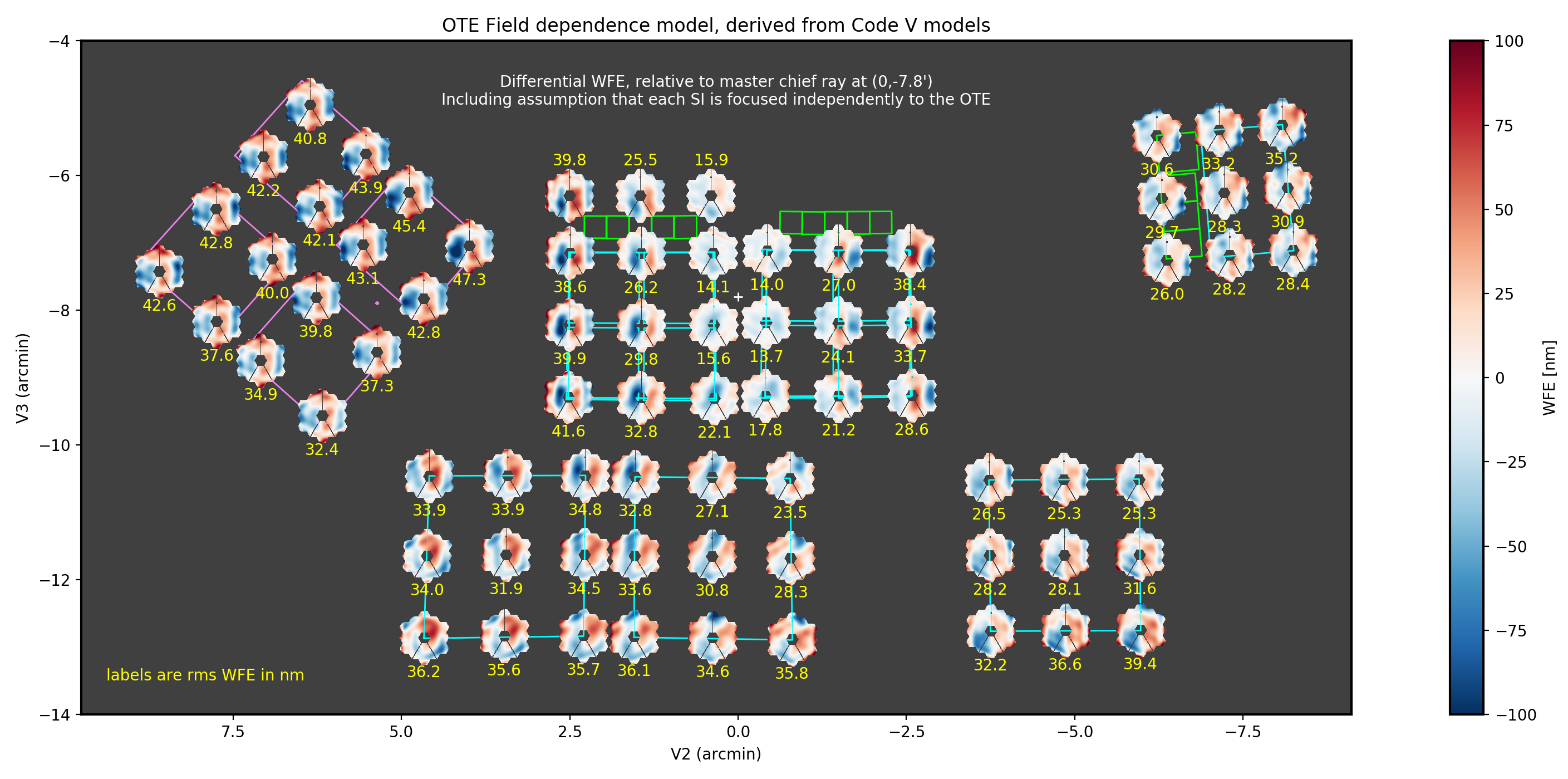
Field Dependent Aberrations
While the OTE is designed to have low aberrations across all of the science instruments, it has small intrinsic aberrations which furthermore vary across the field. This is true even if all mirrors are aligned perfectly, due to design residuals and the as-built mirror surface quality. For the as-built WFE, a particularly significant contributor is the tertiary mirror. Because this is not at a pupil plane, different portions are illuminated for different field points. Surface print-through of manufacturing artifacts into the tertiary mirror surface then results in increased field dependent WFE.
In an effort to capture the contribution of these field-dependent aberrations a polynomial model of the field dependent aberrations was derived, based on the as-built OTE optical model Revision H, which includes measured surface errors of the optical elements. This optical model was used in the CodeV lens design and analysis software package to generate OPD maps capturing the variation of the OTE’s aberrations across the fields of each of the science instruments. Each of these OPD maps were fit to a set of Zernike polynomials so that the wavefront was represented by a small number of coefficients, varying at each field point. These variations are captured by fitting these varying Zernike coefficients to a second set of polynomials. Since the fields are generally rectangular, a set of two-dimensional Legendre polynomials were used for this field-fit. Legendres are well-suited for this task because they are orthonormal over a rectangle and JWST’s science instrument fields are also rectangular. The resulting model can be used to interpolate the OTE WFE at any field point.
Any field variations in focus will be compensated for as part of focusing each SI. This SI focus optimization is taken into account in the OTE WFE model by the simple expedient of removing the average defocus across each SI’s full field of view.
Click to enlarge figures
For the above figure, and all others on this page, click the figure to view it larger and full screen.
NIRCam
Imaging
NIRCam is one of the more complicated classes in webbpsf, and has several unique selectable options to model the two copies of NIRCam each with two channels.
The detector attribute can be used to select between any of the ten detectors,
A1-A5 and B1-B5. Additional attributes are then automatically set for channel
(“short” or “long”) and module (“A” or “B”) but these cannot be set directly;
just set the desired detector and the channel and module are inferred
automatically.
The choice of filter also impacts the channel selection: If you choose a
long-wavelength filter such as F460M, then the detector will automatically
switch to the long-wave detector for the current channel. For example, if the
detector was previously set to A2, and the user enters nircam.filter = "F460M"
then the detector will automatically change to A5. If the user later selects
nircam.filter = "F212N" then the detector will switch to A1 (and the user will
need to manually select if a different short wave detector is desired). This
behavior on filter selection can be disabled by setting nircam.auto_channel = False.
NIRCam class automatic pixelscale changes
The pixelscale will automatically toggle to the correct scale
for LW or SW based on user inputs for either detector or filter.
If you set the detector to NRCA1-4 or NRCB1-4, the scale will be set for
SW, otherwise for NRCA5 or NRCB5 the pixel scale will be for LW.
If you set the filter attribute to a filter in the short wave channel,
the pixel scale will be set for SW, otherwise for a filter in the long wave
channel the scale will be set for LW.
The intent is that the user should in general automatically get a PSF with the appropriate pixelscale for whatever instrument config you’re trying to simulate, with no extra effort needed by the user to switch between NIRCam’s two channels.
Note that this behavior is not invoked for monochromatic calculations; you can’t just iterate over calc_psf calls at different wavelengths and expect it to toggle between SW and LW at some point. The workaround is simple, just set either the filter or detector attribute whenever you want to toggle between SW or LW channels.
Coronagraph Masks
The coronagraph image-plane masks and pupil-plane Lyot masks are all included as options. These are based on the nominal design properties as provided by the NIRCam team, not on any specific measurements of the as-built masks. The simulations of the occulting mask fields also include the nearby neutral density squares for target acquisitions.
WebbPSF won’t prevent users from simulating configuration using a coronagraph image mask without the Lyot stop, but that’s not something that can be done for real with NIRCam.
Note, the Lyot masks have multiple names for historical reasons: The names ‘CIRCLYOT’ and ‘WEDGELYOT’ have been used since early in WebbPSF development, and can still be used, but the same masks can also be referred to as “MASKRND” and “MASKSWB” or “MASKLWB”, the nomenclature that was eventually adopted for use in APT and other JWST documentation. Both ways work and will continue to do so.
The NIRCam class can automatically switch its aperturename attribute when a
coronagraphic mask is selected, to select the aperturename for the appropriate
coronagraphic subarray. The detector reference pixel location will also update
to the center of the coronagraphic subarray. This behavior on image mask or
pupil mask selection can be disabled by setting nircam.auto_aperturename =
False.
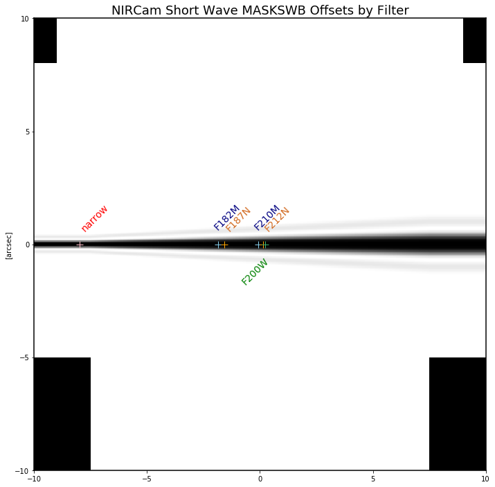
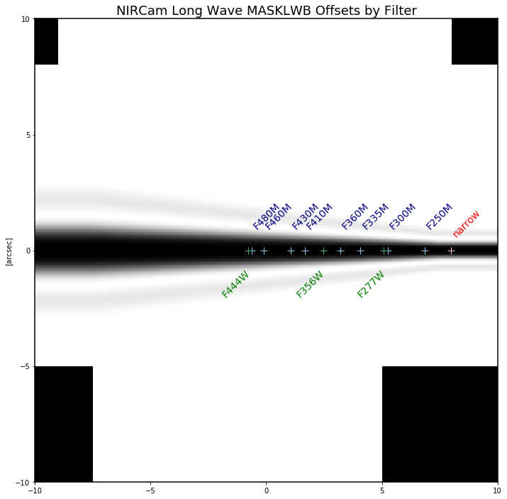
Offsets along the MASKLWB and MASKSWB masks:
Each allowable filter has its own default location along one of these masks. The appropriate offset is automatically selected
in WebbPSF based on the currently selected filter name. If you want to do something different, you can
set the bar_offset option:
>>> nc.options['bar_offset'] = 2.0    # Offsets 2 arcseconds in +X along the mask
or
>>> nc.options['bar_offset'] = 'F480M'  # Use the position for F480M regardless of the currently selected filter
Note that just because you can simulate such arbitrary position in WebbPSF does not mean you can easily actually achieve that pointing with the flight hardware.
NIRCam class automatic detector position setting for coronagraphy
Each coronagraphic mask is imaged onto a specific area of a specific detector. Setting the
image mask attribute to a coronagraphic mask (e.g. MASKLWB or MASK335R) will
automatically configure the detector and detector_position attributes appropriately
for that mask’s field point. Note, this will also invoke the automatic pixelscale functionality
to get the right scale for SW or LW, too.
Weak Lenses for Wavefront Sensing
WebbPSF includes models for the three weak lenses used for wavefront sensing, including the pairs of lenses that can be used together simultaneously.
The convention is such that the “negative” 8 waves lens is concave, the “positive” two lenses are convex. Thus positive weak lenses move best focus in front of the detector, or equivalently the electric field imaged on the detector becomes behind or beyond best focus. Negative weak lenses move best focus behind the detector, or equivalently the image on the detector is moved closer to the OTE exit pupil than best focus.
Note that the weak lenses are in the short wave channel only; webbpsf won’t stop you from simulating a LW image with a weak lens, but that’s not a real configuration that can be achieved with NIRCam.
SI WFE
SI internal WFE measurements are from ISIM CV3 testing (See JWST-RPT-032131 by David Aronstein et al.) The SI internal WFE measurements are distinct for each of the modules and channels. When enabled, these are added to the final pupil of the optical train, i.e. after the coronagraphic image planes. For field-points outside of the measurement bounds, WebbPSF performs an extrapolation routine.
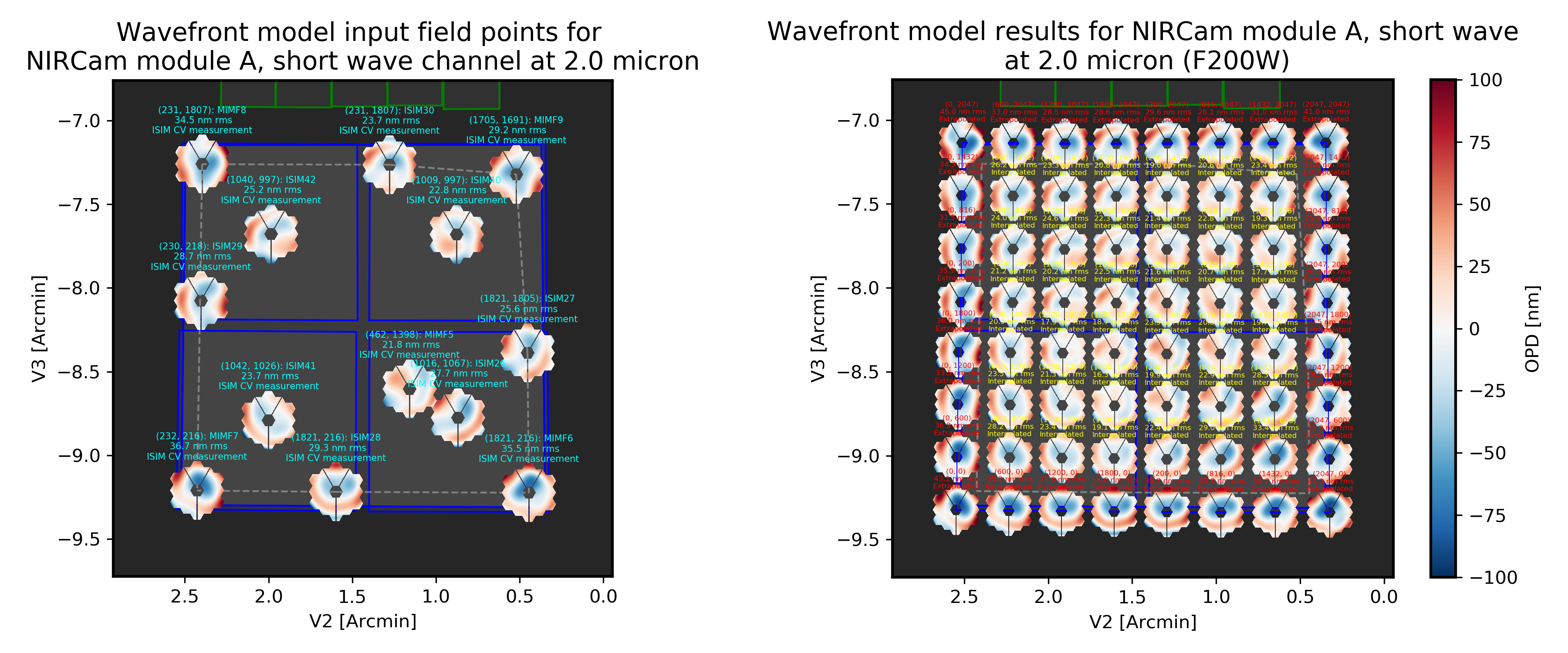
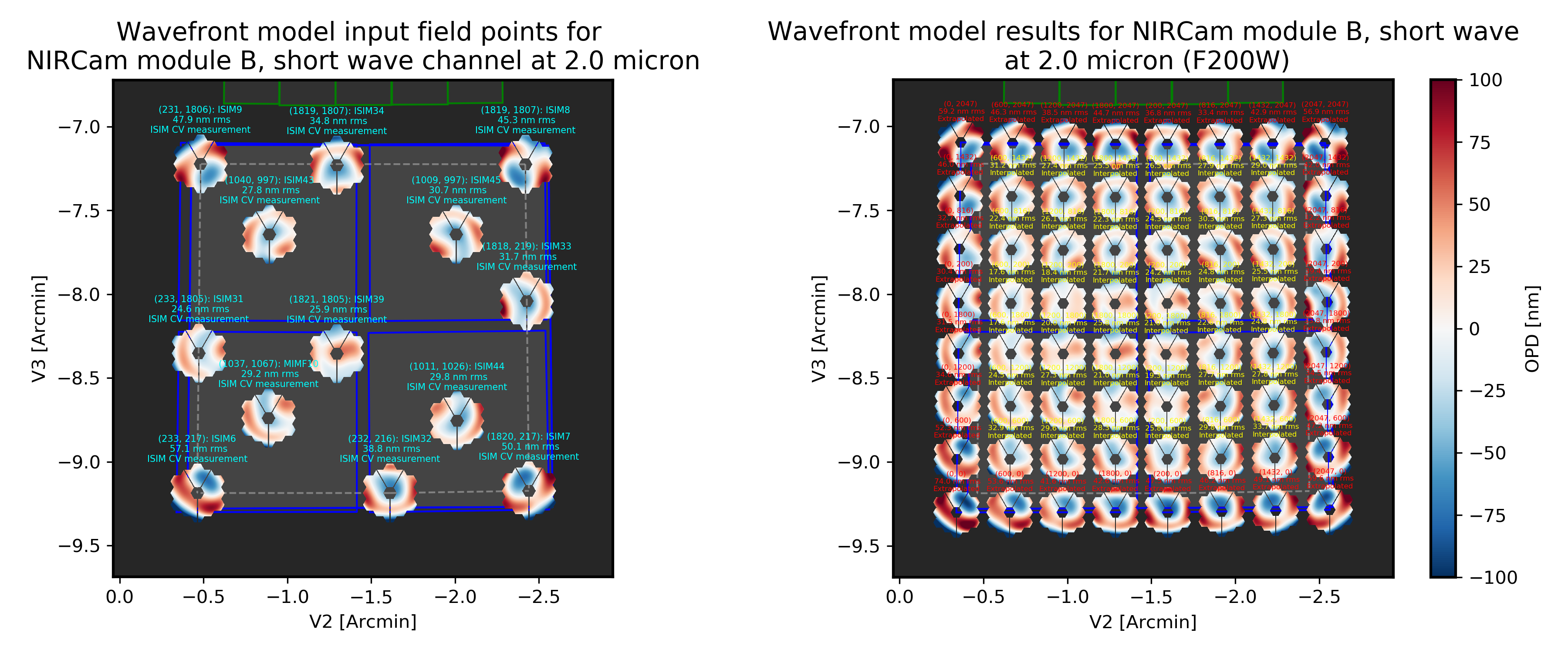
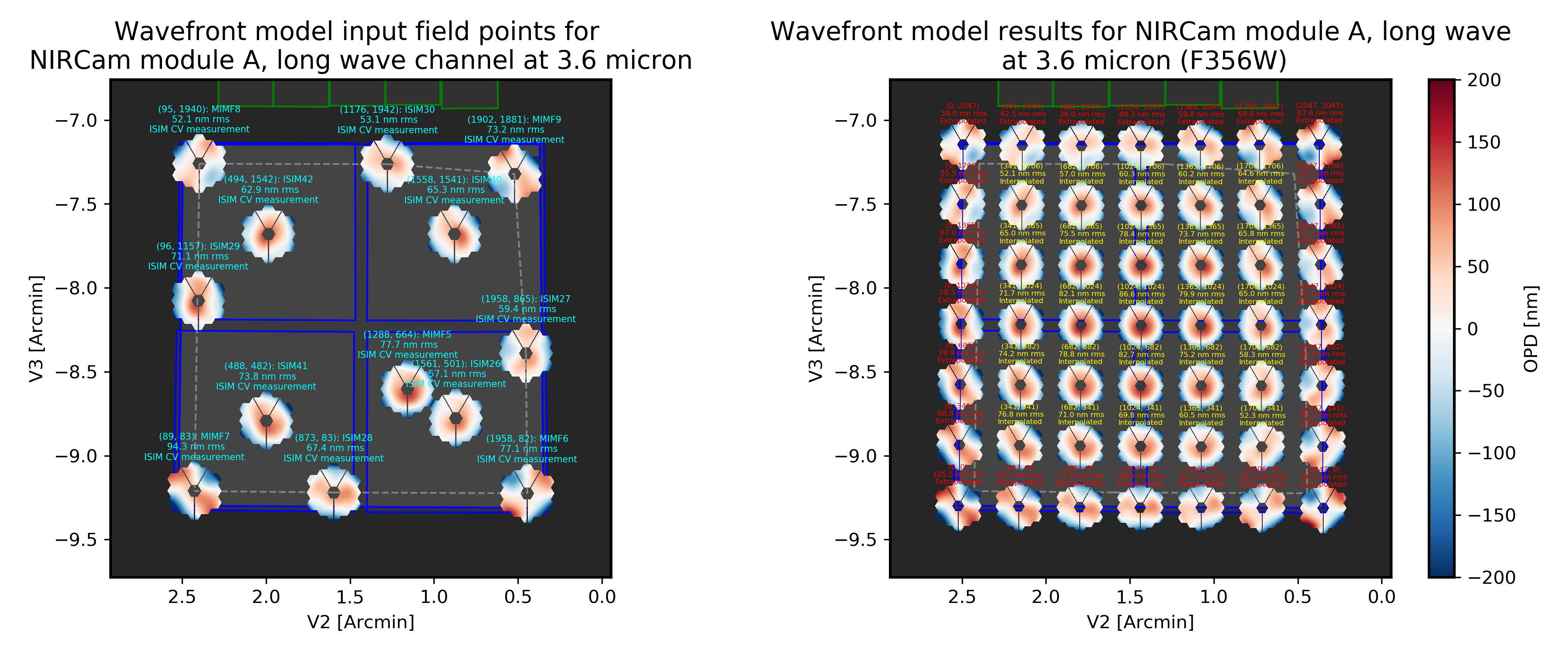

Instrument WFE models for NIRCam. Click for full size.
The coronagraph field points are far off axis, and this comes with significant WFE added compared to the inner portion of the NIRCam field of view. While SI WFE for imaging mode were measured directly from the instrument during ISIM CV3, the coronagraphic WFE maps were built based on the NIRCam Zemax optical model. This model was first validated in imaging mode, and then the appropriate optical elements were inserted to produce the coronagraphic configuration. In this case, both modules were assumed have the exact same (albeit, mirrored) field-dependent WFE maps. Note, this substantial WFE occurs physically after the coronagraphic focal plane spots in NIRCam, and is modeled as such in WebbPSF.
Wavelength-Dependent Focus Variations
NIRCam’s wavelength-dependent defocus was measured during ISIM CV2 at a given field point (See JWST-RPT-029985 by Randal Telfer). Overall, the measurements are consistent with predictions from the nominal optical model. The departure of the data from the model curve has been determined to be from residual power in individual filters. In particular, the F323N filter has a significant extra defocus; WebbPSF includes this measured defocus if the selected filter is F323N.
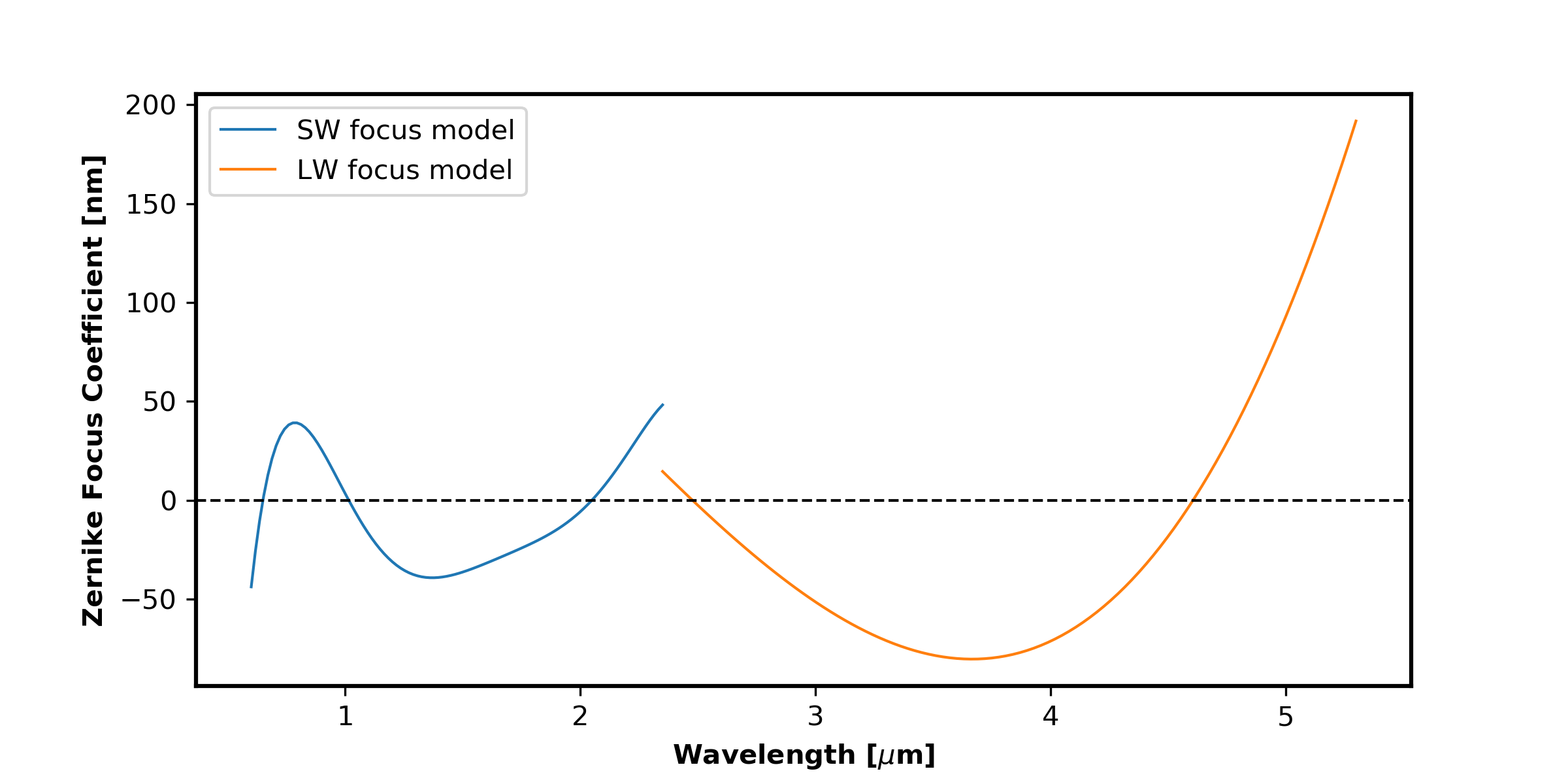
Instrument focus models for NIRCam. Click for full size.
All SI WFE maps were derived from measurements with the F212N and F323N filters. WebbPSF utilizes polynomial fits to the nominal focus model to derive focus offset values relative to these narrowband filters for a given wavelength. The derived delta focus is then translated to a Zernike focus image, which is subsequently applied to the instrument OPD map.
NIRSpec
Imaging and spectroscopy
WebbPSF models the optics of NIRSpec, mostly in imaging mode or for monochromatic PSFs that can be assembled into spectra using other tools.
This is not a substitute for a spectrograph model, but rather a way of simulating a PSF as it would appear with NIRSpec in imaging mode (e.g. for target acquisition). It can also be used to produce monochromatic PSFs appropriate for spectroscopic modes, but other software must be used for assembling those monochromatic PSFs into a spectrum.
Slits: WebbPSF includes models of each of the fixed slits in NIRSpec (S200A1, S1600A1, and so forth), plus a few patterns with the MSA: (1) a single open shutter, (2) three adjacent open shutters to make a mini-slit, and (3) all shutters open at once. Other MSA patterns could be added if requested by users.
By default the pupil_mask is set to the “NIRSpec grating” pupil mask. In
this case a rectangular pupil mask 8.41x7.91 m as projected onto the primary is
added to the optical system at the pupil plane after the MSA. This is an
estimate of the pupil stop imposed by the outer edge of the grating clear
aperture, estimated based on optical modeling by Erin Elliot and Marshall
Perrin.
SI WFE
SI internal WFE measurements are from ISIM CV3 testing (See JWST-RPT-032131 by David Aronstein et al.).
The ISIM CV3 data on their own do not indicate how the sources of WFE are distributed within the NIRSpec optical train. For simulation purposes here, the SI WFE measurements are allocated as 1/3 in the foreoptics, prior to the MSA image plane, and 2/3 in the spectrograph optics, after the MSA image plane. This follows a recommendation from Maurice Te Plate of the NIRSpec team, based on metrology and testing of the NIRSpec flight model optics.
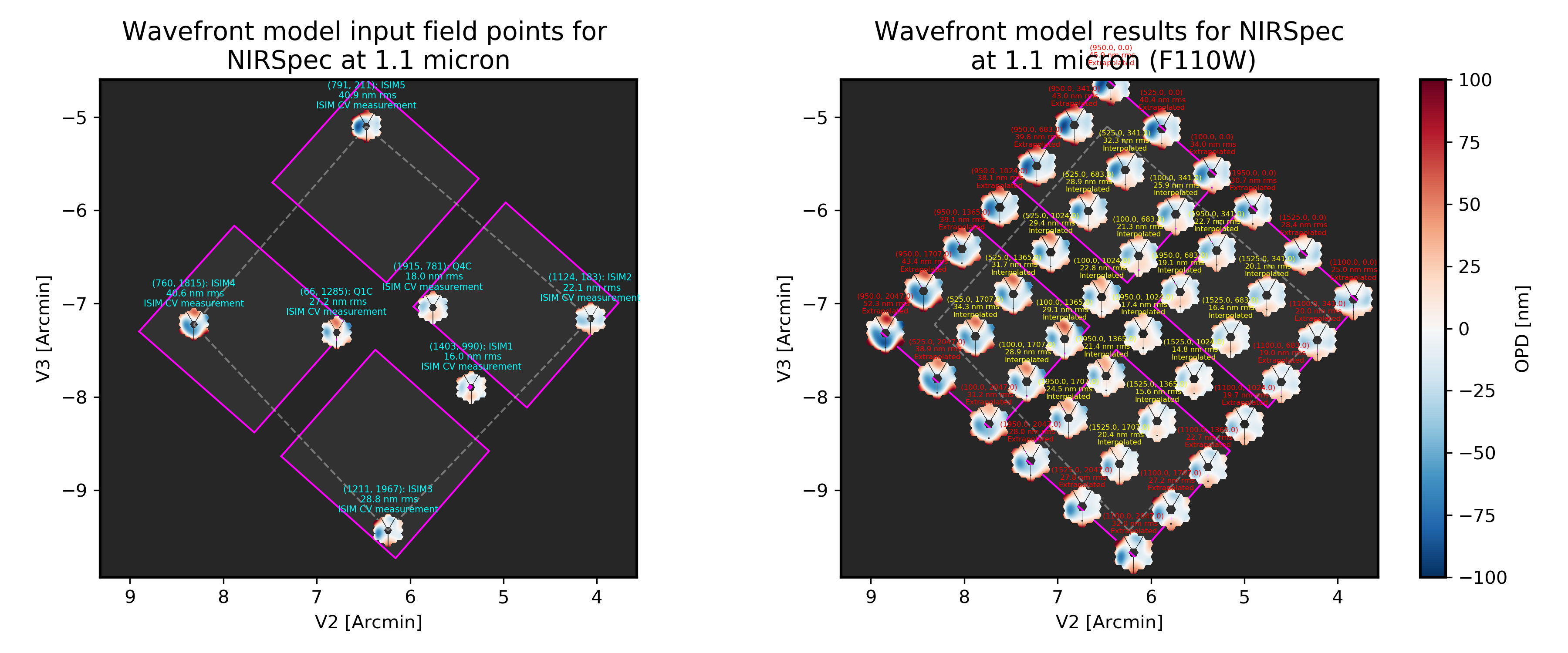
Instrument WFE models for NIRSpec. Click for full size.
NIRISS
Imaging and AMI
WebbPSF models the direct imaging and nonredundant aperture masking interferometry modes of NIRISS in the usual manner.
Note that long wavelength filters (>2.5 microns) are used with a pupil obscuration which includes the pupil alignment reference fixture. This is called the “CLEARP” pupil.
Based on the selected filter, WebbPSF will automatically toggle the
pupil_mask between “CLEARP” and the regular clear pupil (i.e.
pupil_mask = None).
AMI mask geometry is as provided to the WebbPSF team by Anand Sivaramakrishnan. To match the orientation of the mask as installed in the flight hardware, the simulated mask model was flipped in X coordinates as of the spring 2019 version of WebbPSF; thanks to Kevin Volk and Deepashri Thatte for determining this was necessary to match the test data.
Slitless Spectroscopy
WebbPSF provides preliminary support for the single-object slitless spectroscopy (“SOSS”) mode using the GR700XD cross-dispersed grating. Currently this includes the clipping of the pupil due to the undersized grating and its mounting hardware, and the cylindrical lens that partially defocuses the light in one direction.
Warning
Prototype implementation - Not yet fully tested or verified.
Note that WebbPSF does not model the spectral dispersion in any of NIRISS’ slitless spectroscopy modes. For wide-field slitless spectroscopy, this can best be simulated by using WebbPSF output PSFs as input to the aXe spectroscopy code. Contact Van Dixon at STScI for further information. For SOSS mode, contact Loic Albert at Universite de Montreal.
The other two slitless spectroscopy grisms use the regular pupil and do not require any special support in WebbPSF; just calculate monochromatic PSFs at the desired wavelengths and assemble them into spectra using tools such as aXe.
Coronagraph Masks
NIRISS includes four coronagraphic occulters, machined as features on its pick-off mirror. These were part of its prior incarnation as TFI, and are not expected to see much use in NIRISS. However they remain a part of the physical instrument and we retain in WebbPSF the capability to simulate them.
SI WFE
SI internal WFE measurements are from ISIM CV3 testing (See JWST-RPT-032131 by David Aronstein et al.).
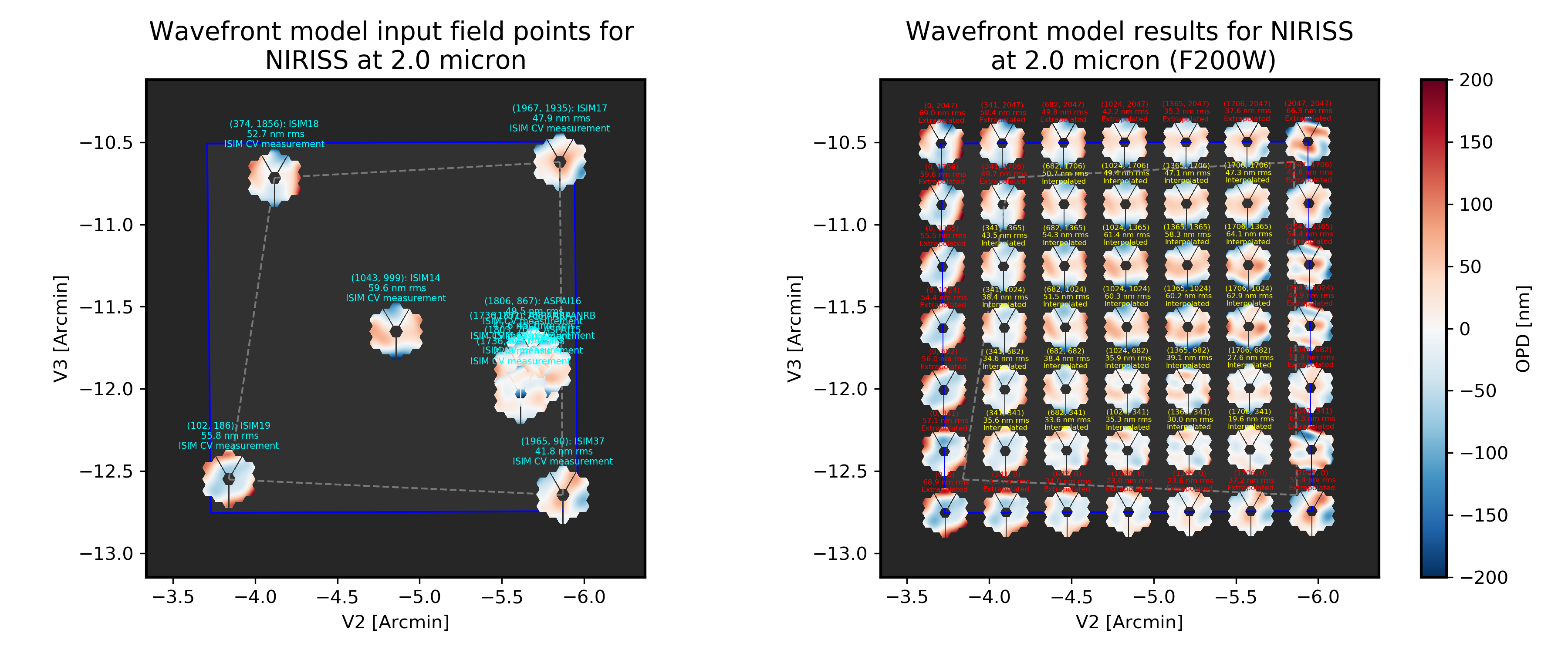
Instrument WFE models for NIRISS. Click for full size.
MIRI
Imaging
WebbPSF models the MIRI imager; currently there is no specific support for MRS, however monochromatic PSFS computed for the imager may be used as a reasonable proxy for PSF properties at the entrance to the MRS slicers.
MIRI detector cross artifact
The MIRI imager’s Si:As IBC detector exhibits a so-called “cross artifact”, particularly at short wavelengths (5-8 microns), due to internal diffraction of photons within the detector substrate itself. See Gaspar et al. 2021 for details. WebbPSF implements a simplified model for this effect, following the approach described by Glasse et al. in MIRI technical report MIRI-TN-00076-ATC_Imager_PSF_Issue_4.pdf. The model coefficients have been adjusted to better match the cross artifact amplitudes from WebbPSF to the MIRI Calibration Data Product reference PSFs.
Note
Where to find Results from the Cross Artifact Model
The cross artifact is added alongside the geometric distortion step, after the optical propagation. The results are stored in FITS extensions 2 and 3 (ext names OVERDIST and DET_DIST for oversampled and detector sampled, respectively not in the default 0th extension which is the raw oversampled PSF. E.g.:
miri = webbpsf.MIRI()
psf = miri.calc_psf()
webbpsf.display_psf(psf, ext=3)
result = psf['DET_DIST'].data   # This is the PSF with the cross artifact model included

Comparison of models for the MIRI detector cross artifact. Click for full size. Shown are the MIRI Calibration Data Product PSFs (Left), the WebbPSF results (Center) and their difference. The cross artifact is negligible at wavelengths beyond ~12 microns.
Coronagraphy
WebbPSF includes models for all three FQPM coronagraphs and the Lyot
coronagraph. In practice, the wavelength selection filters and the Lyot stop are
co-mounted. WebbPSF models this by automatically setting the pupil_mask
element to one of the coronagraph masks or the regular pupil when the filter
is changed. If you want to disable this behavior, set miri.auto_pupil = False.
The MIRI class can automatically switch its aperturename attribute when a
coronagraphic mask is selected, to select the aperturename for the appropriate
coronagraphic subarray. The detector reference pixel location will also update
to the center of the coronagraphic subarray. This behavior on image mask
selection can be disabled by setting miri.auto_aperturename = False.
LRS Spectroscopy
WebbPSF includes models for the LRS slit and the subsequent pupil stop on the
grism in the wheels. Users should select miri.image_mask = "LRS slit" and miri.pupil_mask = 'P750L'.
That said, the LRS simulations have not been extensively tested yet;
feedback is appreciated about any issues encountered.
SI WFE
SI internal WFE measurements are from ISIM CV3 testing (See JWST-RPT-032131 by David Aronstein et al.).
The SI internal WFE measurements, when enabled, are added to the final pupil of the optical train, i.e. after the coronagraphic image planes.
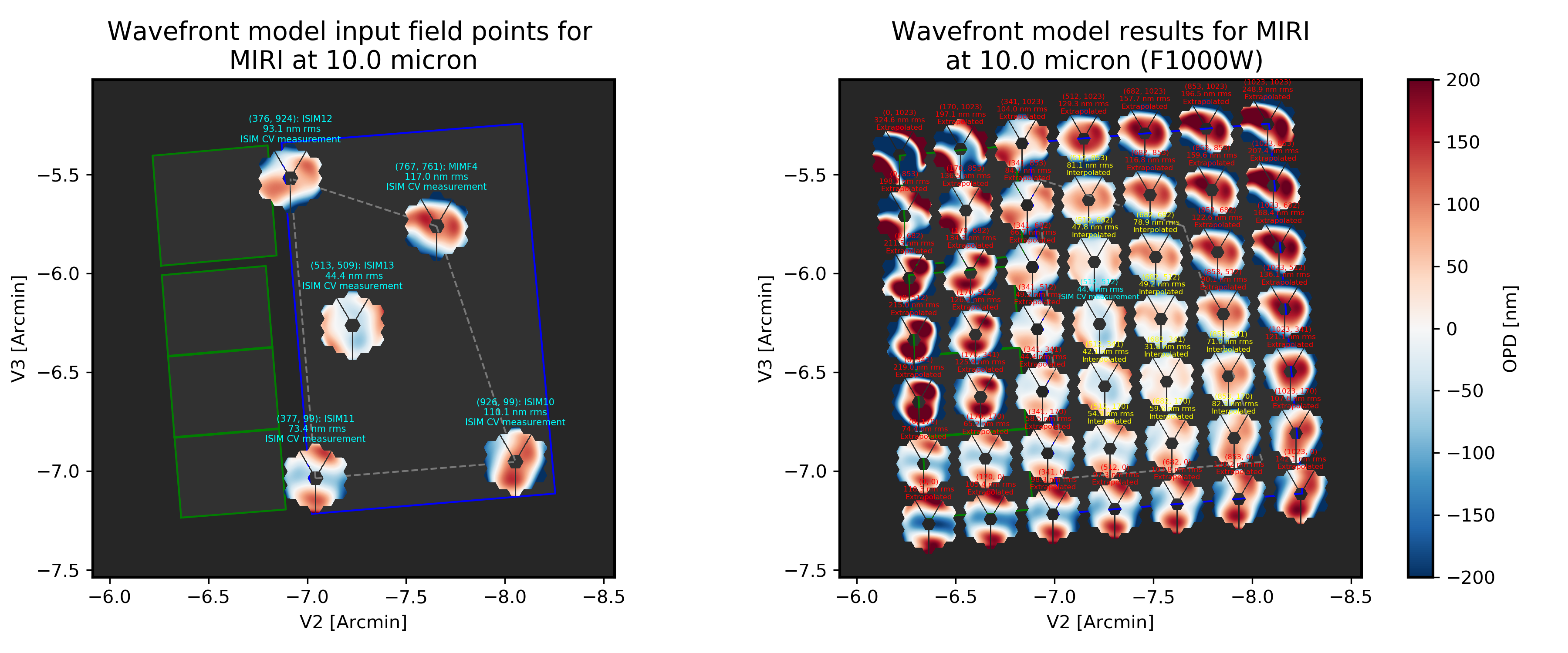
Instrument WFE models for MIRI. Click for full size.
Minor Field-Dependent Pupil Vignetting
TODO Add documentation here of this effect and how WebbPSF models it.
A fold mirror at the MIRI Imager’s internal cold pupil is used to redirect light from the MIRI calibration sources towards the detector, to enable flat field calibrations. For a subset of field positions, this fold mirror slightly obscures a small portion of the pupil. This is a small effect with little practical consequence for MIRI PSFs, but WebbPSF does model it.
FGS
The FGS class does not have any selectable optical elements (no filters or image or pupil masks of any kind). Only the detector is selectable, between either ‘FGS1’ or ‘FGS2’.
SI WFE
SI internal WFE measurements are from ISIM CV3 testing (See JWST-RPT-032131 by David Aronstein et al.).
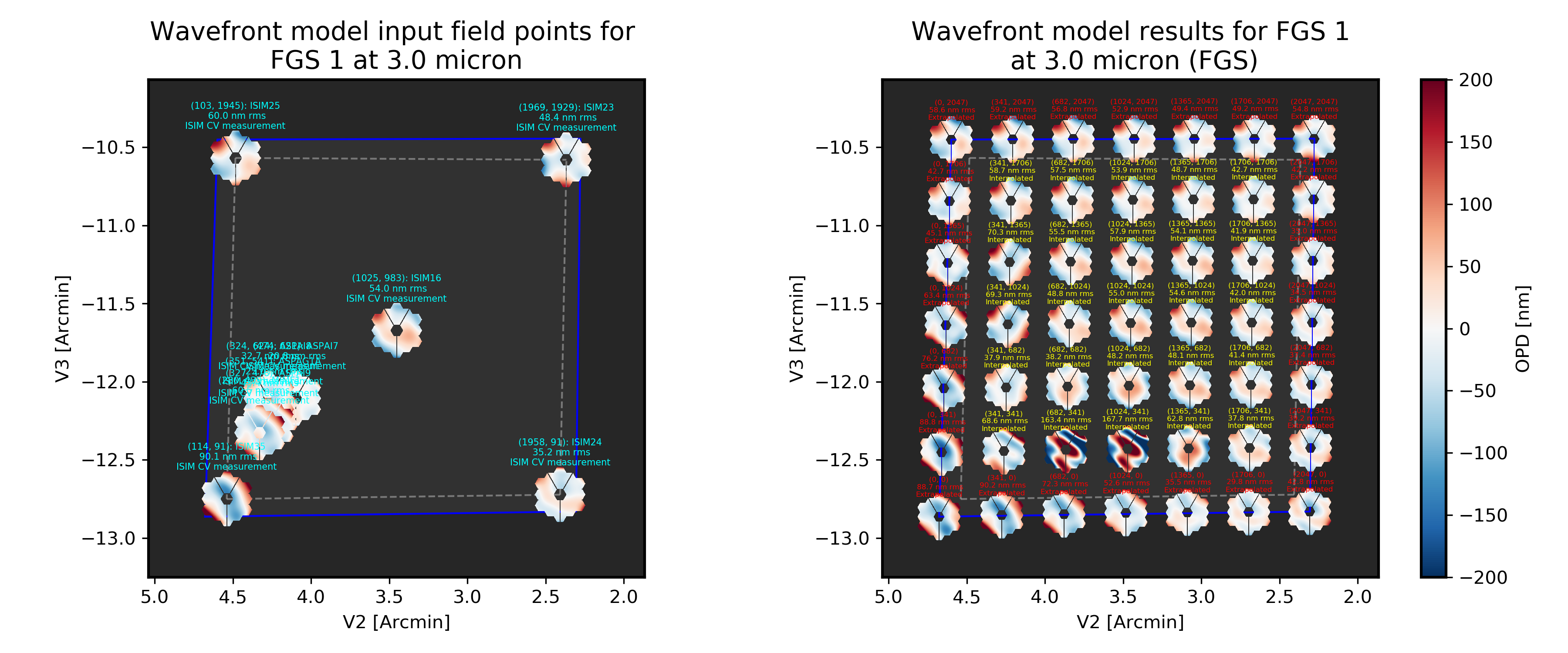
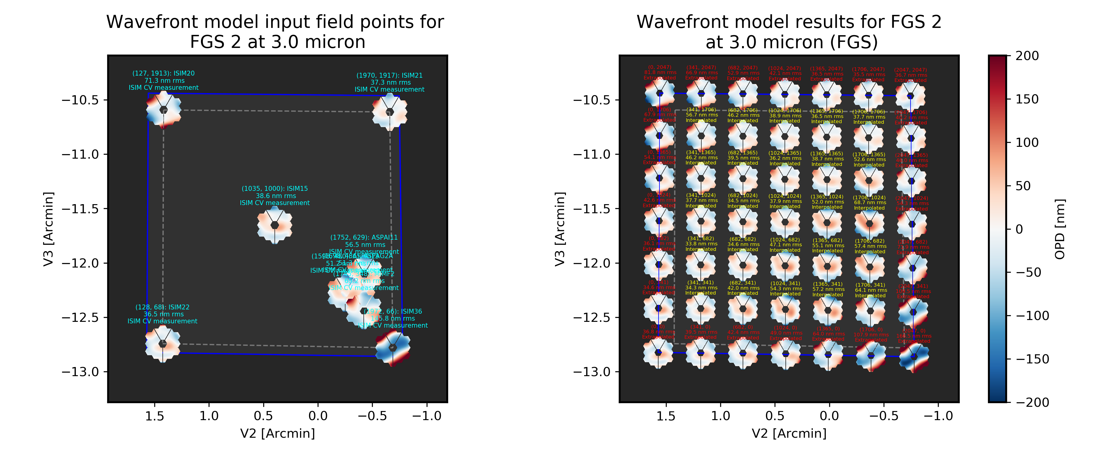
Instrument WFE models for FGS. Click for full size.